

SCHWING PUMPS UTILIZED IN “FLOAT-IN” CONSTRUCTION

The new Braddock Dam, located on the Monongahela River outside of Pittsburgh, PA, has been under construction since 1999 when inspectors discovered signs of deterioration on the existing fixed crest dam. Joint venture general contractors J.A. Jones Construction Company, Charlotte, NC, and Traylor Bros., Inc., Evansville, IN, are working with designer Ben C. Gerwick, Inc., San Francisco, and project owner U.S. Army Corps of Engineers, Pittsburgh Division, to construct the new gated dam 100 yards up the Monongahela River from its 100-year old predecessor. Since the beginning of construction, concrete pumps have played a critical role in the construction of the new dam.
The new Braddock Dam is being constructed using a relatively new construction method known as the “Float-In” or “In-the-Wet” construction. The method uses off-site prefabrication combined with float-in of large precast segments onto pre-installed foundations. In the case of the Braddock Dam, there are six phases to construction: pre-fabrication, launch, transport, outfitting, immersion, and infill.
There are several advantages over conventional “In-the-Dry” dam construction methods. First, lower construction costs are achieved by transferring a significant amount of work from the river to on-land construction. With traditional dam construction, contractors would begin with the building of coffers and barriers to drain the river in preparation for construction. With the float-in method, the Corps of Engineers estimates that they will save the project owners up to $15 million in excavation, piling and labor costs and 18 months of work. By transferring construction out of the marine environment, the designers also lessen environmental impact and provide higher quality work in a more controlled environment.
For the construction of the Braddock Dam, Traylor-Jones set up shop in a basin dug near the bank of the Ohio River in Leetsdale, 27.5 down river from the new dam site. The contractor brought in cranes and Schwing concrete pumping equipment to construct two portions of the dam. Concrete at the casting sight was furnished by Beaver Concrete Company, Rochester, PA.
In the summer of 2001, Traylor-Jones began the prefabrication phase by erecting the foundation on which to build the segments. This was achieved by utilizing a grid of concrete footings with gravel between them, allowing water to pass through the gravel and push up on the bottom of the dam upon launching. This eliminated stress building up at the outside edges of the dam, allowing the segment to float free of the foundation.
The segments themselves were constructed using 438 precast panels interconnected in a grid pattern and weighing four to 70 tons each. The vertically placed panels were assembled for each segment and tied together with a monolithic post-tensioned base slab. Joints between all of the panels were filled with concrete to from a rigid cell. The design created a boat-like structure with water-tight interior compartments. The two-level casting basins allowed crews to form the segments into recessed closed-bottom boxes to match the specs of the foundation caissons and ensure secure set-down. Despite the weight and volume of the two segments, the Law of Buoyancy guaranteed the segments would float even at 11,185 and 8,585 tons respectively.
Traylor-Jones called on Howard Concrete Pumping, a local Schwing dealer who supplied three truck-mounted concrete boom pumps and operators at the casting facility. Howard utilized a 32 XL, 36-meter and a KVM 42 to fill in the joints between the pre-cast panels and complete the cast-in-place portions of the segments. Mike Moriarty, Engineer for Traylor, said the long reach of the booms was necessary considering the height and close proximity of the pre-cast panels. “It would have taken us considerably longer using the crane and bucket method, and precise placement was important on this project,” he said. Three pours were necessary to complete the 12” thick monolithic slab on the first and larger of the two segments, a total of 3,800 cubic yards of concrete.
As the Leetsdale crew worked to complete the segments, crews were constructing the dam landing at Braddock. Crews rock-socketed 89 drill shafts measuring 78” in diameter under 40” of water. Twelve landing caissons were designed to match the six recessed closed-bottom boxes on each of the segments.
On July 9, 2001, the Army Corps closed portions of the Ohio and Monongahela rivers to traffic and released a nearby dike to flood the basin and launch the first segment. The segment was the larger of the two, measuring in at 333’ long by 106’ wide and 40’ high, the size of a football field. At 7:30 am on July 28, 2001, the 11,185-ton segment was transported by two towboats 27.5 miles up the Ohio River to an outfitting pier in Duquesne. At the outfitting pier, crews worked another four months adding an additional 24 vertical feet of cast-in-place to the segment’s piers. Once again, pumps were the only practical method to grout the precast joints and continue the monolithic basin. Moriarty explained why the contractor waited to complete the segment until the outfitting stage. “We had this 333 x 106-foot segment that was drafting at 15 feet all the way to Duquesne. At certain points in the transport, we were clearing the riverbed by as little as six inches. We would have never been able to execute a successful transport with that extra 24 feet of concrete.”
A seven-winch mooring system was also installed on three piers of the segment and connected to fixed anchor piles located in various positions in the river. A water-ballast system was also installed so that water could be pumped into the segment’s cells simultaneously to provide level sinking.
On December 5, 2001, the segment was transported from Duquesne to the Braddock Dam site by two towboats and carefully positioned at a predetermined location in close proximity to the final set-down area. The mooring lines from the fixed anchor piles were attached to the positioning winches on the dam segment. Once the segment was positioned properly over the foundation caissons, water was slowly pumped into the interior compartments, increasing the weight of segment and sinking it into place.
Several hydraulic jacking devices were used to make adjustments needed in the segment’s final positioning, and the segment was leveled. Once the segment was properly placed, the pile tops, drill shafts and underbase of the dam were grouted with 21,000 cubic yards of tremie concrete.
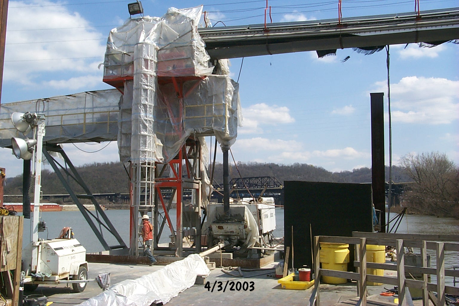
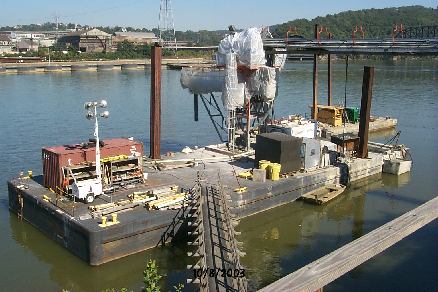
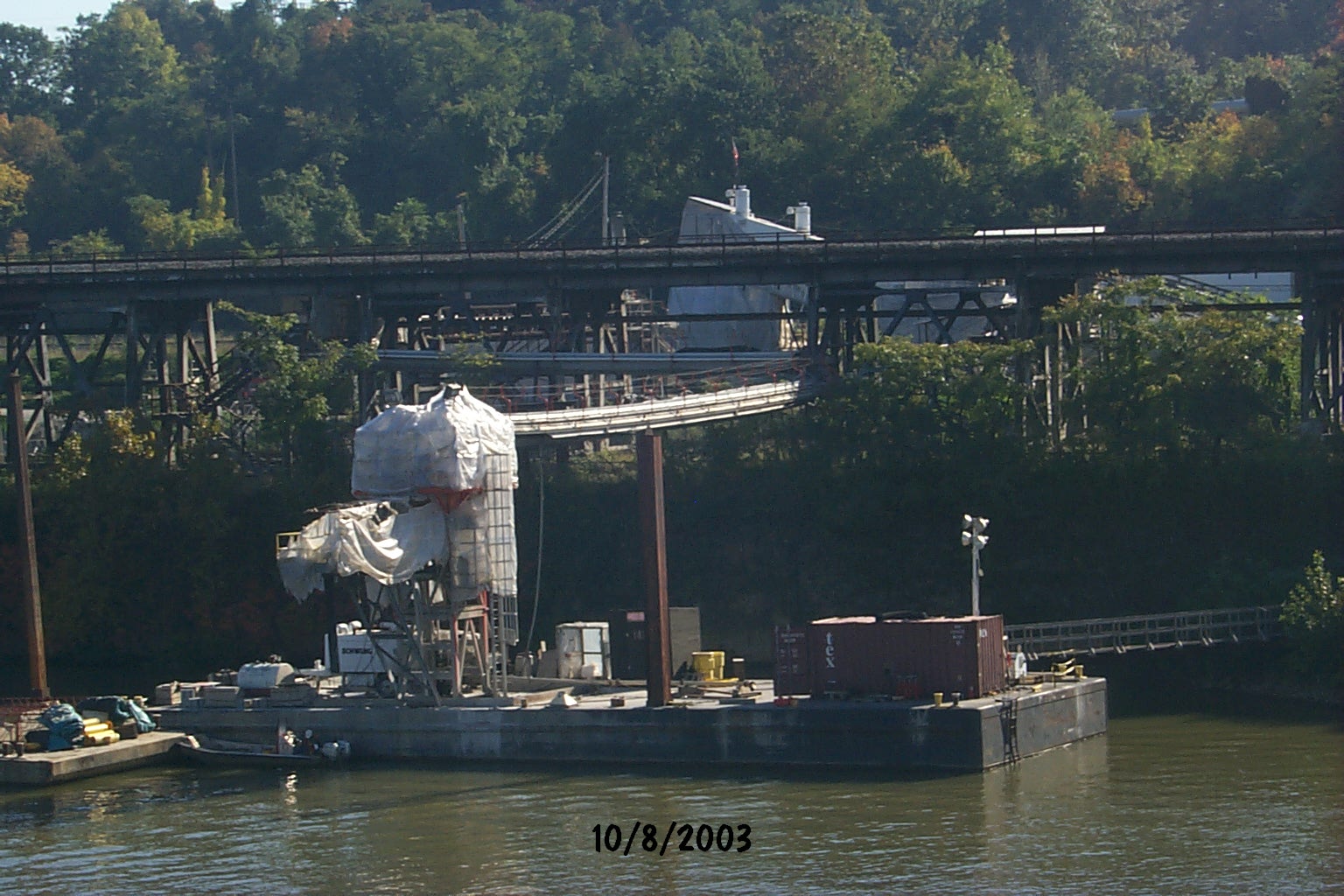
Traylor purchased a Schwing BPA 8000 trailer pump to place the tremie concrete. The 8000 was set up on a floating barge, which was permanently moored into place for construction. The pump was supplied with a nine-inch slump concrete via 500 feet of conveyor belt. The long four-section belt was necessary due to several railroad tracks that run up and down the banks of the river. “We had to go over three sets and under two other sets of tracks,” said Moriarty.
To meet the spec, crews from Jones-Traylor produced the mix at their on-site batch plant. Mike Moriarty explained the complicated eleven constituent mix. “We called it Mix #1, or our underwater mix,” he said. The mix contained 118 pounds of cement, 141 pounds of fly ash, 424 pounds slag, 280 pounds of water, a total 100 ounces of water reducers, and the most important element, an anti-washout agent.
Wayne Jones, Project Manager for Traylor, commented on the concrete mixes involved in the grouting and infill of the segment. “These are very elaborate mixes we’re dealing with. They’re very chemically dependent, and can’t just be sourced from a typical commercial concrete supplier.”
Crews used the belt system to supply the 8000 pump, which in turn pushed the sticky mix through 700 feet of pipeline to a Con-Forms Spider. Using its 60-foot boom reach, the Spider distributed the concrete into hoppers placed on the segment.
Once the underbase grouting was completed, Traylor went to work displacing the water used to sink the segment with the same Mix #1 concrete. Crews used the same belt-supplied 8000 trailer pump to supply the Spider. This time, the hoppers receiving the mix were placed on the segment in a checkerboard pattern to ensure even distribution. Project Manager Wayne Jones estimated that upon take off from Leetsdale, the segment weighed in at around 20 million pounds. After displacing the water with the tremie concrete, crews switched to a more conventional mix, “Mix #2,” to place a total 4 million pounds of concrete as additional ballast.
Seven months later, the second segment, measuring in at 265 feet long, 104 feet wide and 43 feet high, embarked from the Leetsdale Casting Facility for the same transport to Duquesne. After a few months at the outfitting facility, the 8,585-ton segment was positioned at the dam site in June of 2002.
Traylor will complete their pumpable concrete placements with a 4,000 cubic yard pour in March. The permanent raising of the Braddock Pool surrounding the dam is scheduled for Summer 2006.

